GATE -2002 Civil Engg paper
Printed From: One Stop GATE
Category: GATE Previous Years Test Papers - Discuss Here
Forum Name: ME Papers
Forum Discription: ME Previous Year GATE Papers to can discussed here.
URL: http://forum.onestopgate.com/forum_posts.asp?TID=66
Printed Date: 20Aug2025 at 5:58pm
Topic: GATE -2002 Civil Engg paper
Posted By: Arpita
Subject: GATE -2002 Civil Engg paper
Date Posted: 05Jan2007 at 4:44pm
|
1 The value of the following improper integral is
2.
3 The Laplace Transform of the following function is
(A) (B) (c) (d) 4 The limit of the following sequence as n ® ¥ is:
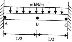
5 A steel beam (with a constant El, and span L) is fixed at both ends and carries a uniformly distributed load (w kN/m), which is gradually increased till the beam reaches the stage of plastic collapse (refer to the following figure). Assuming 'B' to be at mid-span, which of the following is true,
6 As per the provisions of IS 456-2000, in the limit state method for. design of beams, the limiting value of the depth of neutral axis in a reinforced concrete beam of effective depth 'd given as: .
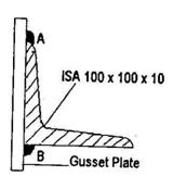
7 ISA 100 x 100 x 10 mm (Cross sectional area = 1908 mm 2) serves as tensile member. This angle is welded to a gusset plate along A and B appropriately as shown. Assuming the yield strength of the steel to be 260 N/ mm2 the tensile strength of this member can be taken to be approximately, (A) 500 kN
(B) 300 kN (C) 225 kN (D) 375 kN
8 ISA 100 x 100 x 10 mm (Cross sectional area = 1908 mm 2) is welded along A and B (Refer to figure for question 2.7), such that the lengths of the weld along A and B are 1 1 and 1 2, respectively. Which of the following is a possibly acceptable combination of 1 1 and 1 2.
(A) 1 1 = 60 mm and 1 2 = 150 mm (B) 1 1= 150 mm and 1 2 = 60 mm (C) 1 1 = 150 mm and 1 2 = 150 mm (D) Any of the above, depending on the size of the weld.
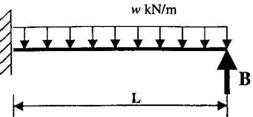
9 In the propped cantilever beam carrying a uniformly distributed load of w N/m, shown in the following Figure, the reaction at the support B is
(A) (B) (C) (D)
10 An infinite slope is to be constructed in a soil. The effective stress strength parameters of the soil are c=O and f '= 30°. The saturated unit weight of the slope is 20 kN/m 3 and the unit weight of water is 10 kN/m 3. Assuming that seepage is occurring parallel to the slope, the maximum slope angle for a factor of safety of 1.5 would be:
(A) 10.89° (B) 11.30°
11 If the effective stress strength parameters of a soil are c'=10 kPa and 0'=30°, the shear strength on a plane within the saturated soil mass at a point where the total normal stress is 300 kPa and pore water pressure is 150 kPa will be:
12 The time for a clay layer to achieve 85% consolidation is 10 years. If the layer was half as thick, 10 times more permeable and 4 times more compressible then the time that would be required to achieve the same degree of consolidation is:
13 In a triaxial test carried out on a cohesion less soil sample with a cell pressure of 20 kPa, the observed value of applied stress at the point of failure was 40 kPa. The angle of internal friction of the soil is:
------------- For more papers visit: http://onestopgate.com/gate-preparation/ - http://onestopgate.com/gate-preparation/ |